FSK Modulation
FSK - frequency shift keying - which means keying by shifting the frequency. And right away I’ll include a few basic terms I’ll be using.
frequency deviation
The maximum offset of frequency from the carrier wave / reference frequency.
bitrate
The speed of data transmission expressed in bits per unit of time.
symbol
The smallest unit of a modulated signal that carries a defined number of information bits.
baudrate
The transmission speed expressed in symbols per unit of time.
Simplified diagram of an FSK transmitter

And here’s an important note: implementations of the modulator can vary - what matters is the final effect, which is a wave at a specific frequency or a specific frequency shift at the output, representing a given symbol.
There can be a hardware implementation, where the modulator is a VCO, and the modulating signal is a control voltage - higher voltage means a higher output frequency from the VCO.
It can also be a software implementation, where we generate the signal using a sine function (and cosine if we’re working with I/Q samples).
The carrier wave - just to make this clear - doesn’t actually appear in the output signal. The FSK modulator affects the carrier wave by changing its frequency. In this way, we get a modulated carrier wave (with a shifted frequency).
In a software implementation, it can be hard to imagine the carrier wave. You can think of it as a reference frequency (f0), relative to which we calculate the frequency shifts. So in the output of such a modulator, the carrier doesn’t physically exist, but it acts as a variable in the software that defines the reference frequency, used as part of the argument for sine or cosine functions when generating the signal.
Here’s a kind of pseudocode:
for (unsigned int i = 0; i < sampleBuffSize; ++i)
{
   symbol = // extracted from the data depending on the encoding.

   // Selection of the frequency representing a specific symbol relative to f0
   freq = f0 - fDeviation + 2 * fDeviation * symbol / (symbolSize - 1);
   phase += (2 * PI / sampleRate) * freq;

   I[i] = cos(phase);
   Q[i] = sin(phase);
}
Modulating signal
This is the signal we want to modulate, transmit, and then reconstruct in the receiver. In the case of standard FM modulation, the modulating signal will be sound collected by a microphone and then, in the form of an electrical signal, passed to a modulator or an ADC converter to turn it into a digital signal. Of course, between the microphone and the modulator, there might be other elements, for example, an amplifier.
So, in the case of sound transmission, the modulating signal will be analog or discrete (sampled), where one symbol - the value of the signal at a given moment - can take many different states.
In the case of data transmission, the value of the modulating signal can take 2 states - in the case of 2FSK modulation. In such a situation, data is modulated bit by bit.
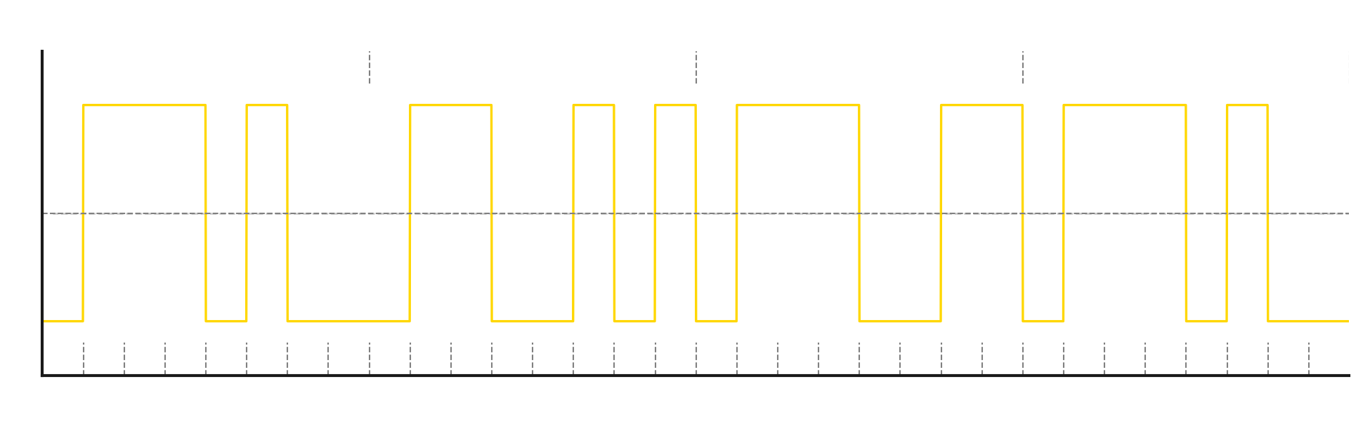
Example of a two state symbol (2FSK)
We want to transmit the text:
“test” -> in binary -> 0’1’1’1’0’1’0’0’0’1’1’0’0’1’0’1’0’1’1’1’0’0’1’1’0’1’1’1’0’1’0’0
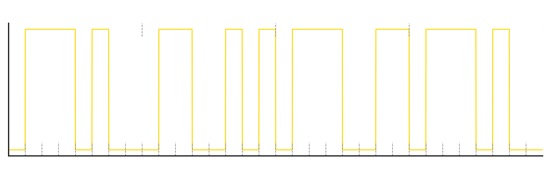
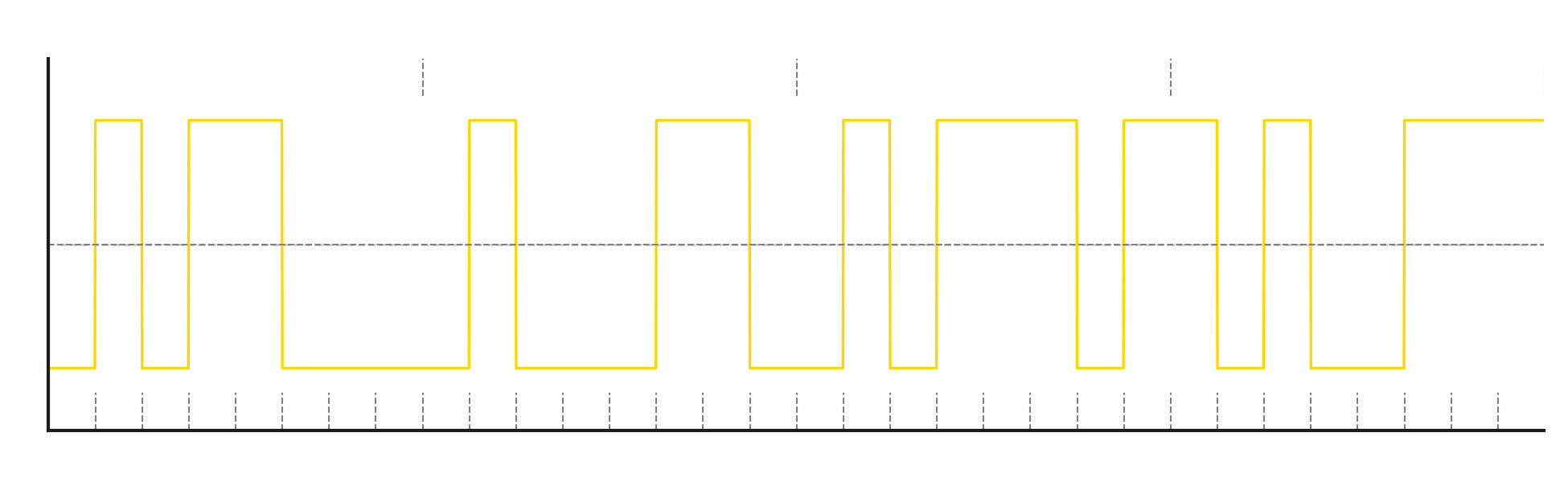
And after modulating the carrier signal:
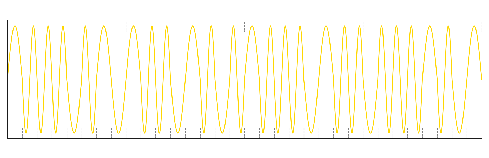
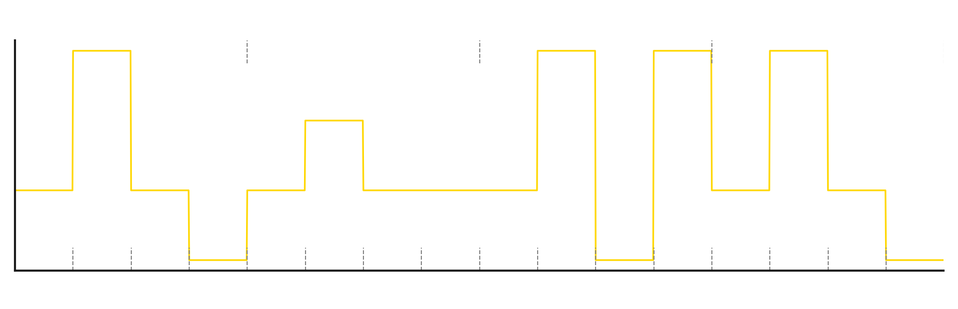
Example of a four state symbol (4FSK)
But there’s nothing stopping us from using more than 2 states for one symbol. For example, we can send data two bits at a time:
“test” -> in binary -> 01110100011001010111001101110100 -> split into two bit chunks -> 01’11’01’00’01’10’01’01’01’11’00’11’01’11’01’00 -> final modulating signal values -> 1’3’1’0’1’2’1’1’1’3’0’3’1’3’1’0
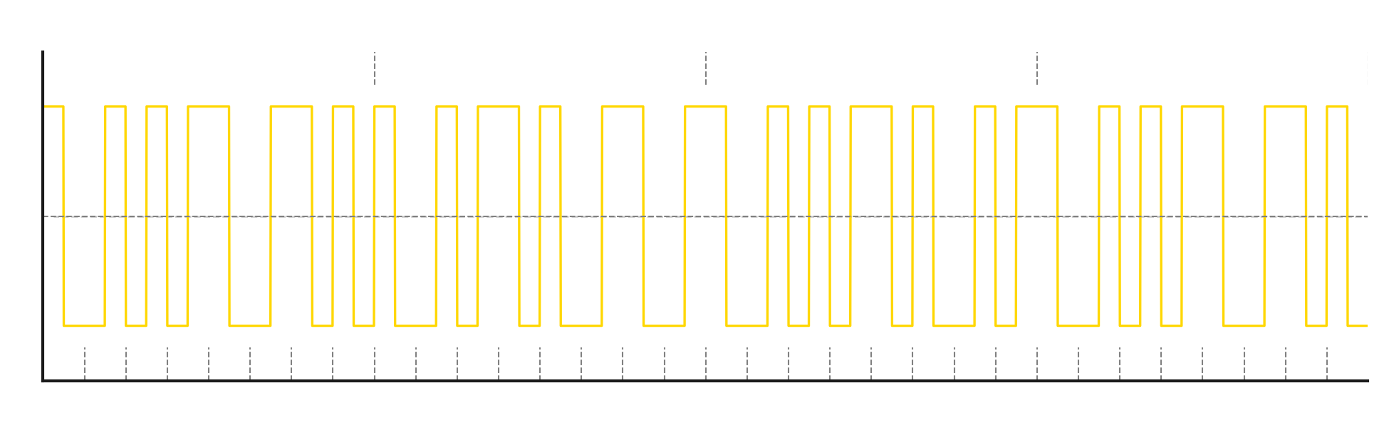
Modulated carrier wave:
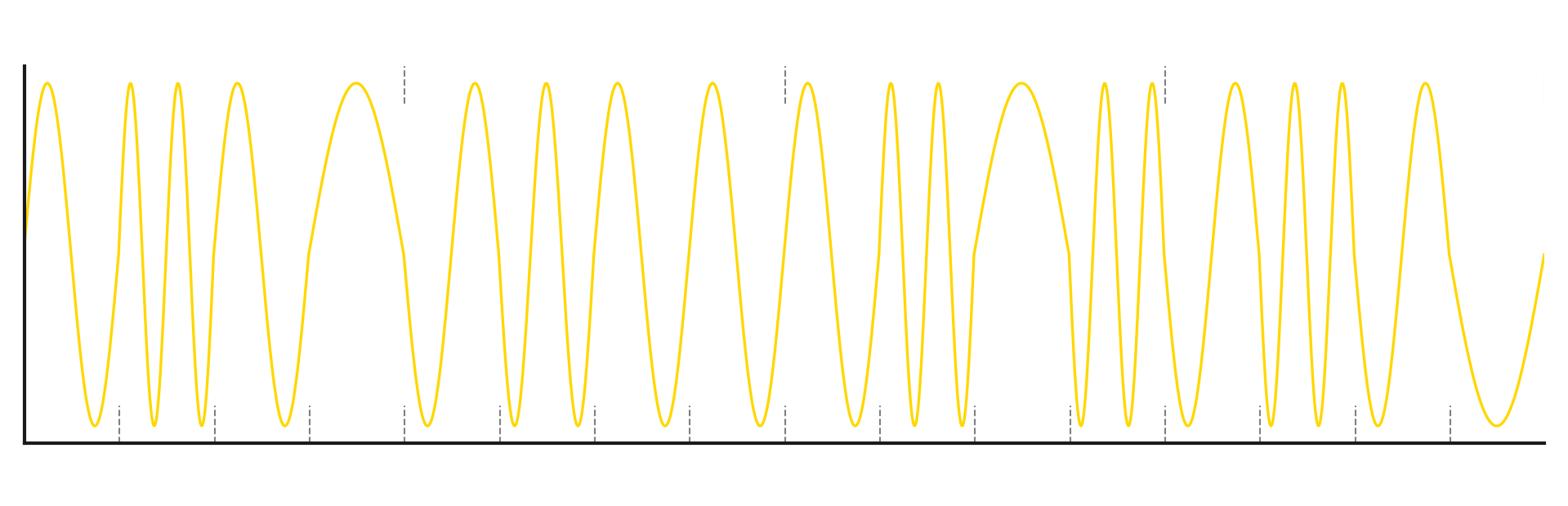
Modulating signal encoding
In the previous examples and diagrams, this part was a bit simplified - we directly converted binary data into modulating signal values. But such encoding - or rather the lack of it - has several drawbacks. First of all, a modulating signal value of 0 would mean the modulator doesn’t alter the carrier wave - so symbol 0 would be sent at the center frequency (directly on the carrier frequency), and symbol 1 would be sent at the deviation frequency, which is the defined frequency offset.
Instead, we usually want the carrier frequency to be the center point, and the modulated symbols on the frequency axis to be symmetrically placed around the carrier frequency. With the same deviation, the maximum offset from the carrier will then be two times smaller.
So, encoding is the method of creating a modulating signal from the data we receive. On one side, we have binary data we want to send, and on the other side, we want to output a modulating signal to the modulator. To visualize this, I’ll expand the previous “simplified FSK transmitter diagram”:

Now I’ll go over encoding types based on binary symbols.
NRZ
Non Return to Zero - so we don’t return to zero. It’s a basic encoding method that solves the problem mentioned earlier. We shift the values of the modulating signal downward so that 0 is placed symmetrically between the high and low states.
To keep things simple, I’ll write NRZ-coded symbols as + for positive and - for negative. So when encoding the binary sequence 010101 in NRZ, we get -+-+-+
These are not specific values, because that depends on how we do the modulation. For example, if we modulate by changing the voltage on a VCO, the + symbol would mean increasing voltage to shift the frequency by the deviation amount, and - would mean decreasing voltage to lower the VCO frequency.
NRZI
Non Return to Zero Inverted - just like in the previous case, we don’t return to zero. But here we don’t copy the input binary stream directly. Instead, we react to the change in bit state compared to the previous one. To illustrate:
Input sequence: 00000000 -> encoded as -------- This means no bit changed, so we encode the sequence with no state changes.
Input sequence: 00001111 -> encoded as ----+---- For the first 4 bits, the signal state stays the same, so we encode -. The fifth bit is 1, which means a change from the previous bit - so we encode +. The next bits are still 1, so there’s no change compared to the previous bit - we go back to encoding -.
This type of encoding makes demodulator implementation simpler because we don’t need to tell the difference between + and - symbols. Just by detecting when the signal crosses zero, we can reconstruct the previously modulated binary sequence.
This encoding is popular in phase modulation, where the demodulator - without any extra reference signal - can’t determine the absolute value of the phase, only its relative changes.
Manchester
So far, we’ve looked at two encoding methods, but they have a certain drawback - a long sequence of 0s or 1s in the data results in no change in the state of the modulating signal, which can lead to synchronization issues on the receiver side. At high data transmission speeds, even a small mismatch between the receiver’s and transmitter’s clocks can cause the receiver to miss a symbol or duplicate one.
Every change in the state of the modulating signal gives a chance for synchronization and helps determine the relative duration of a single symbol.
Manchester encoding solves this problem by using 2 symbols for each bit, where the two symbols always have different states.
For example: We encode 0 as +- And 1 as -+
In exchange for needing twice as many symbols to send the same amount of data, we gain the ability to synchronize even when the input data values don’t change.
Bit stuffing
This is not a direct method of encoding data, but it’s often used with NRZ and NRZI to prevent desynchronization. After a certain number of symbols with no state change, we insert an extra symbol with the opposite state.
Input sequence: +++++++++ After bit stuffing: +++++-++++
In this case, after every 5 repeating symbols, we insert one with the opposite state. To make this work, both the receiver and transmitter must know after how many symbols the extra one is inserted.
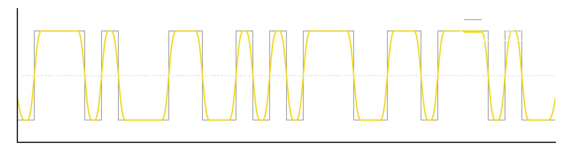
GFSK
Gaussian Frequency Shift Keying - this is a variant of FSK modulation where the modulating signal, before reaching the modulator, is filtered using a Gaussian filter. This smooths out the state changes of the modulating signal.
(G) FSK Simulator
Sources
Esezam PW · FSK · NRZ · Manchester code
Copyright © sq9p.com