Tracker Stefan v2 - Firmware
Main state machine

The architecture of the tracker’s main functionality is based on a state machine - each state is responsible for performing a specific task or group of tasks - (e.g. for the Wait for GPS state, the following tasks are performed: turning on the GPS, waiting for a valid position, turning off the GPS).
After completing a given group of tasks, the state switches to the next one - shown in the diagram using arrows.
Here, between each state transition, there is a configurable delay, during which the tracker and all its components are in sleep mode to save energy.
Power down state
Maybe a bit misleadingly named power down – in this state the tracker is powered, but the processor has put all components to sleep.
In this mode, the tracker can be stored with the battery soldered in. Current consumption is around 10 - 15 µA, which is practically nothing.
The tracker is ultimately designed to operate with a soldered-in battery, so this state is intended to prevent battery discharge between the moment of soldering and the balloon launch.
Entering or exiting the power down state is triggered by pressing the button 5 times.
Each switch between Storage Mode Power Down State and Flight Mode triggers a write to non-volatile memory (FLASH), so that in case of an unexpected tracker reset, correct operation can be restored.
Thanks to this, if a reset occurs during flight (e.g. due to a brief power loss), the tracker will resume operating in the Flight Mode section after the reset.
It then waits until the button on the board is pressed 5 times to enter “Flight Mode”.
TX Position state
Responsible for transmitting the last known position. The tracker configuration includes a Frequency Table: an array with several entries: frequency, mode, position transmission prescaler, and telemetry transmission prescaler.
The prescalers define how many executions of this state should occur before position or telemetry is transmitted. Each entry in the table may have optional geofencing configuration – a few points forming an area on the map where (or outside of which) the position can be transmitted on that frequency.
| Nr | Frequency | Mode | Position Prescaler | Telemetry Prescaler | Geofencing |
|---|---|---|---|---|---|
| 1 | 433.775 | APRS LoRa 300 | (1) | 4 | (not Poland) |
| 2 | 434.855 | APRS LoRa 1200 | (1) | 4 | (Poland) |
| 3 | 432.500 | APRS AFSK | (2) | 8 | (World) |
| 4 | 437.600 | 4FSK Horus | (1) | - | (Poland) |
| 5 | 434.500 | SSTV | 1 | - | World |
| 6 | … | … | … | … | … |
In the Tx position state, the firmware iterates over the configuration table, checking whether the mode in a given entry allows position transmission.
If yes, it checks the Position Prescaler, which determines how often the position should be transmitted (1 - every time, 2 - every second time, 3 - every third pass through the Tx Position state).
Next, if the entry has geofencing enabled, it checks whether the tracker is within (or outside) the required area.
If everything matches, the radio transmits the position according to the frequency and mode defined in that entry.
TX Telemetry state
Basically the same as above, but this part handles telemetry – for entries using the APRS protocol, these include telemetry channel labels and functions that convert values from 8-bit variables (-128 to 127) to the target format.
| Nr | Frequency | Mode | Position Prescaler | Telemetry Prescaler | Geofencing |
|---|---|---|---|---|---|
| 1 | 433.775 | APRS LoRa 300 | 1 | (4) | (not Poland) |
| 2 | 434.855 | APRS LoRa 1200 | 1 | (4) | (Poland) |
| 3 | 432.500 | APRS AFSK | 2 | (8) | (World) |
| 4 | 437.600 | 4FSK Horus | 1 | - | (Poland) |
| 5 | 434.500 | SSTV | 1 | - | World |
| 6 | … | … | … | … | … |
Just like in TX position, but here we check the Telemetry Prescaler – it defines how many cycles must pass before telemetry is transmitted on the given frequency.
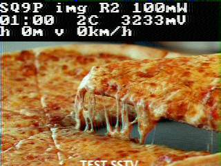
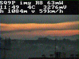
TX SSTV state
images transmission